| This drawing shows
the numbering of the holes. It shows the pictorial view as seen from the top. The squares at A2, D2, A7 and D7 are flea clips. |
 |
| This drawing is again the
top view, this time showing the connections to the flea clips. |
 |
| This drawing is the bottom
view of the perf board. The holes are numbered as seen from the bottom. The heavy black lines are the component leads. |
 |
| This is the current schematic for the Boost converter. The negative power is connected to the emitters and LED cathode. With the values shown, the circuit draws about 18 mA and drives the LED to 5 mA or so. Higher input voltage, up to 3 volts assuming white LED use, pulls more current and therefore produces more light. Changes in values will change performance. Attention should be paid to the inductor, as it is the key in most cases. It needs to be capable of dealing with peak currents and not saturating. |  |
| This drawing is the LM317 based regulator circuit. |  |
This is the schematic for the Low Drop Out (LDO) regulator circuit based on the LM334. The transistor boosts the available current (limited to 10 mA by the IC) to higher levels needed to drive the LED. In the example above the 47 ohm resistor (which is always in circuit) sets a basic current of about 1.5 mA. When the switch is not in the center position (open circuit) either the 10 ohm or 2.2 ohm resistor is put in parallel with it, raising the total current. This gives low, medium and high levels, each regulated. |
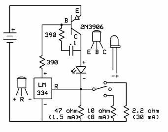 |
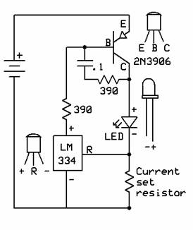
This is the schematic for the Low Drop Out (LDO) regulator circuit based on the LM334. The transistor boosts the available current (limited to 10 mA by the IC) to higher levels needed to drive the LED. The regulator (the LM334) compares the voltage between it’s R and minus leads (caused by the voltage drop across the current set resistor as a result of the actual LED current at that point in time) against an internal reference of approximately .065 Volts. It then drives the transistor more or less to correct the LED current to match the preset value. Thus LED current stays constant for changes in battery or LED voltage. The value (in ohms) needed for any given current is .065 divided by that current (in Amps). |
 |